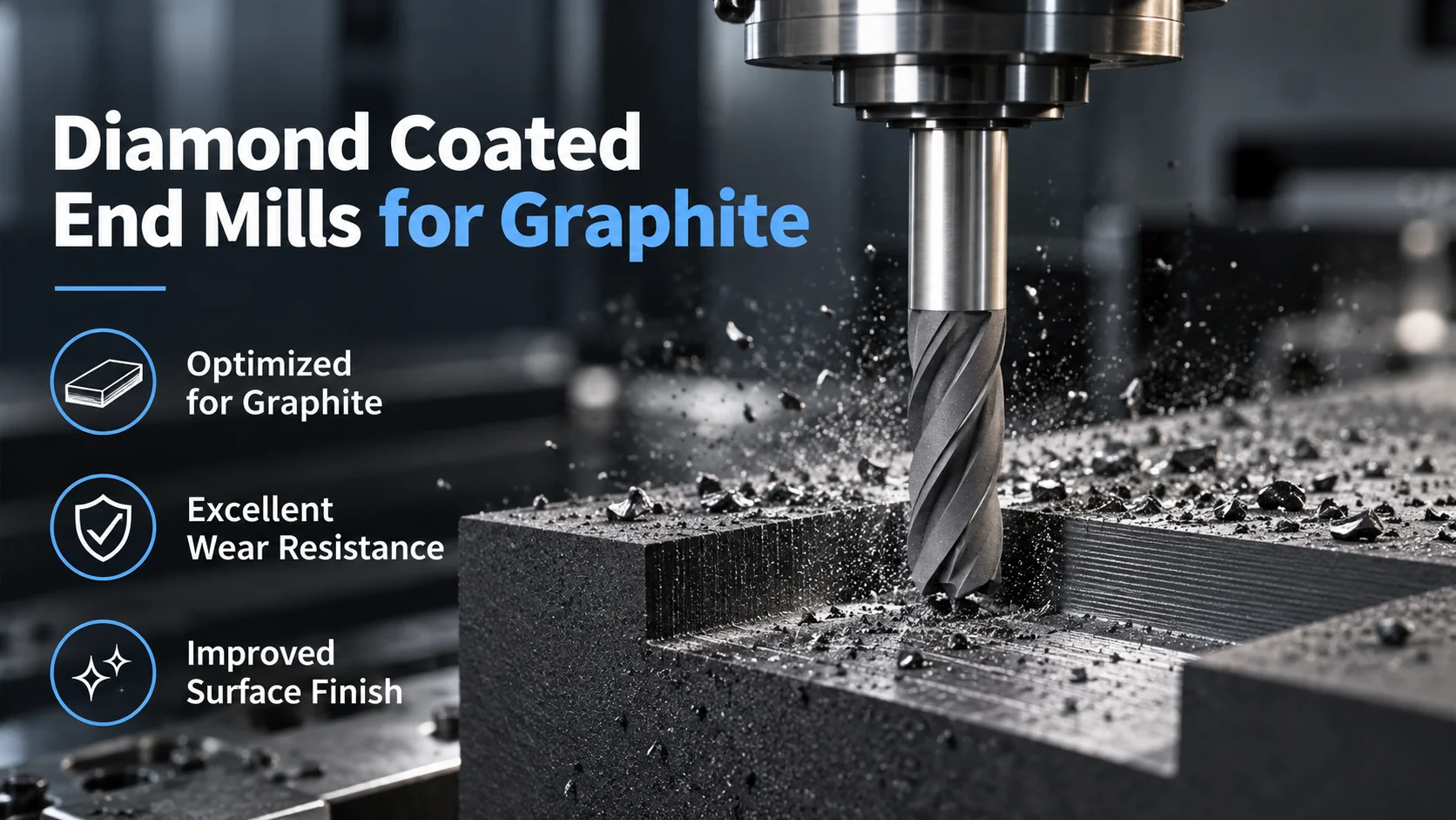
Select a graphite cutter around the feature you must hold: compare diamond coatings, flute count and reach, then validate the process against electrode accuracy and cost per accepted part.
For repeat production of graphite EDM electrodes, a diamond-coated carbide end mill designed for graphite is a strong starting candidate. Choose the cutting shape from the drawing, then verify coated diameter, usable reach and cutting conditions. The best end mill for graphite is the one that holds your critical features through an economical batch—not simply the tool with the lowest price or the most flutes.
A flat pocket, a curved electrode and a narrow rib require different contact geometry. This guide turns those requirements into a selection sequence, with calculation examples and an inspection plan. It is an application guide, not a brand ranking or a claim that one cutter wins every test.
Start with the smallest feature you must hold
Before selecting a coating, identify the smallest internal radius, narrowest slot, deepest wall and tightest dimensional tolerance. These decide which tools can physically machine the part. Record the graphite grade as well: a trial in one grade does not establish performance in another. For EDM electrodes, include the specified electrode geometry and machining allowance; do not confuse an EDM spark-gap allowance with compensation for a worn cutter.
| Feature or operation | Candidate geometry | Check before ordering |
|---|---|---|
| Flat-bottom pocket or straight slot | Square end | Diameter tolerance, corner requirement and full-width cutting conditions |
| Open pocket roughing with permitted fillets | Corner radius | Corner radius fits the drawing and remaining stock |
| Sculpted electrode surface | Ball nose | Ball radius, contact position and finishing stepover |
| Narrow, deep cavity | Relieved or tapered neck | Clearance over the complete toolpath, not just at full depth |
| Thin rib or small detail | Short, small-diameter graphite tool | Runout, remaining support and measurable wear limit |
Use a larger rigid tool to clear accessible stock, then a smaller tool only where the remaining geometry requires it. A small finishing cutter should not inherit unplanned heavy engagement in an internal corner. Simulate rest material and holder clearance before cutting.
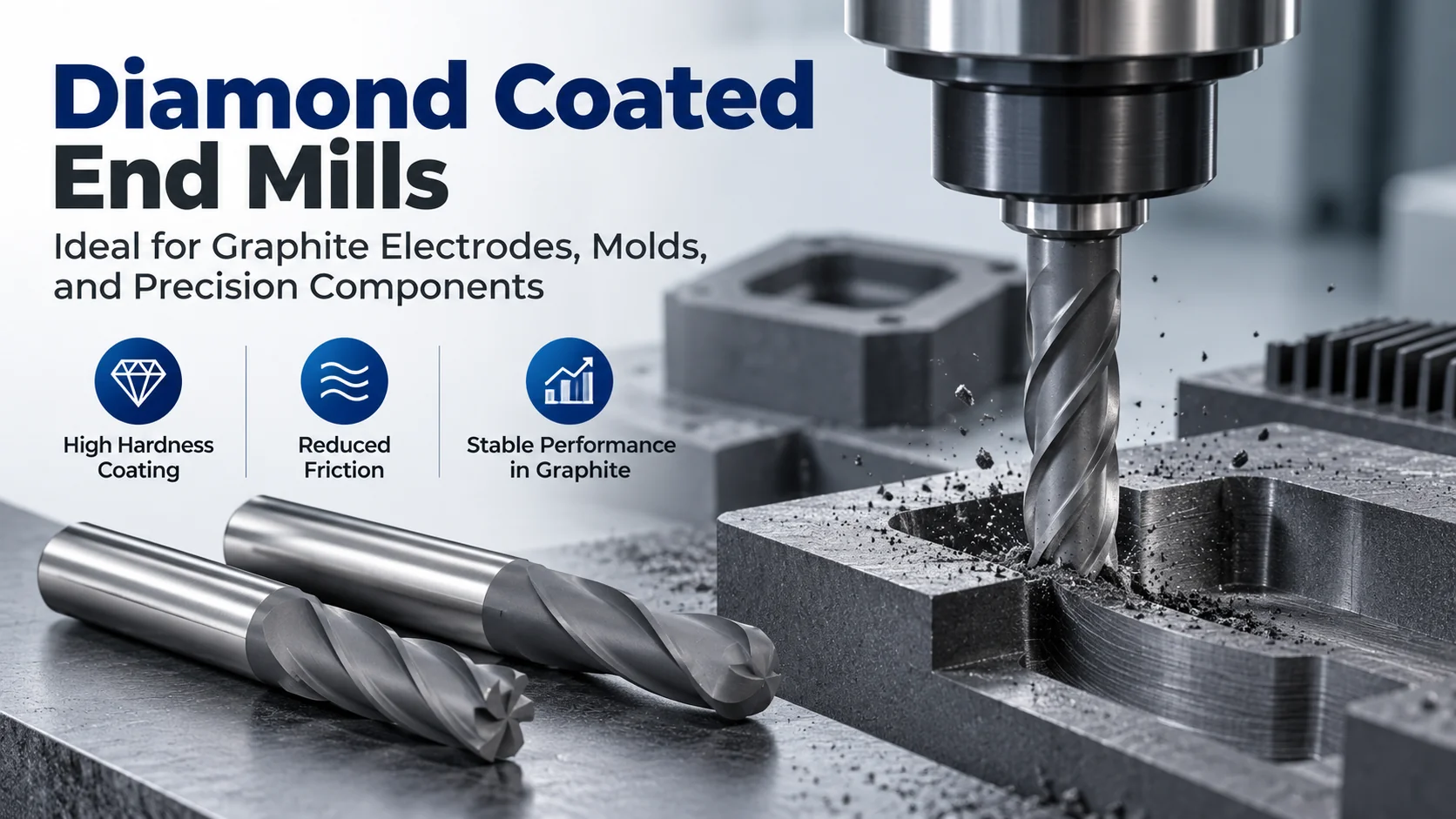
Shop diamond-coated end mills for graphite
Compare all 14 families by cutting shape, reach and diameter. Open a series for dimensions, order codes and cutting references.
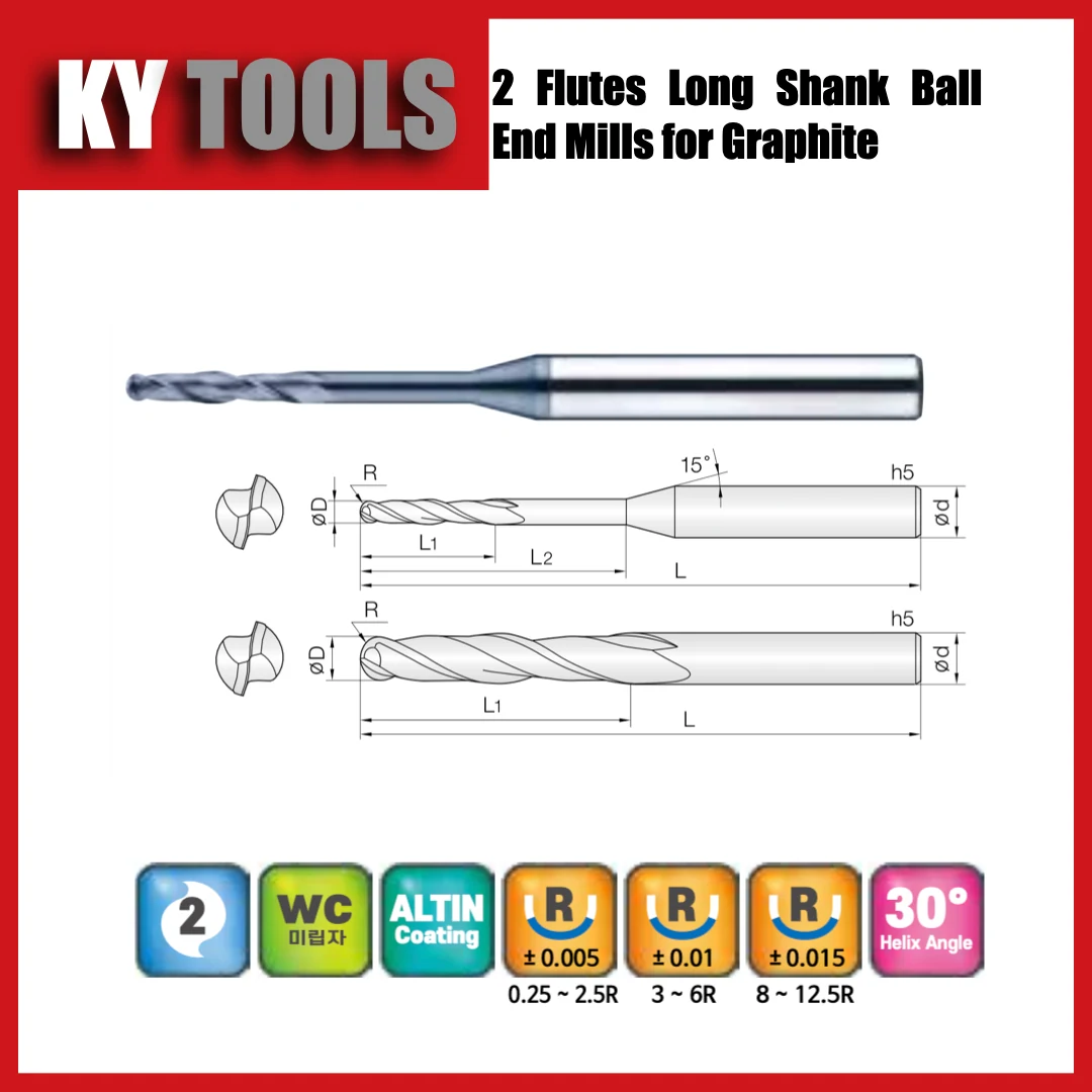
2GBE
2 flutes · Ball nose · Long shank
Ø0.5–25 mm · 77 sizes
View series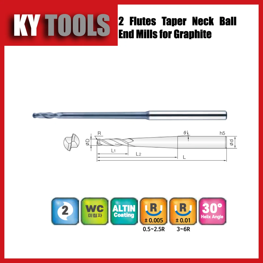
2TGB
2 flutes · Ball nose · Taper neck
Ø1–12 mm · 27 sizes
View series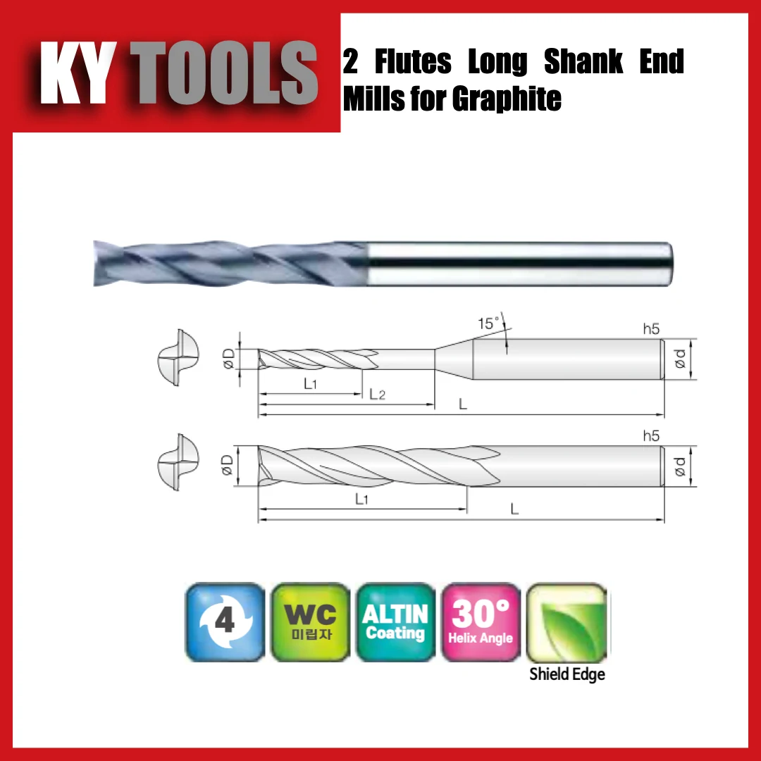
2GEM
2 flutes · Square end · Long shank
Ø0.5–20 mm · 37 sizes
View series4GEM
4 flutes · Square end · Long shank
Ø3–20 mm · 19 sizes
View series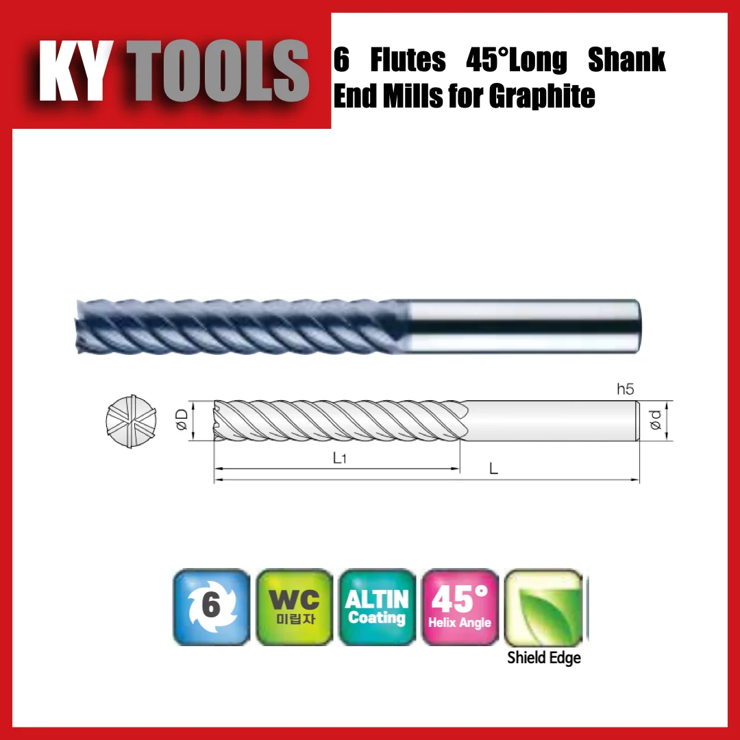
6GEM
6 flutes · Square end · Long shank
Ø6–20 mm · 12 sizes
View series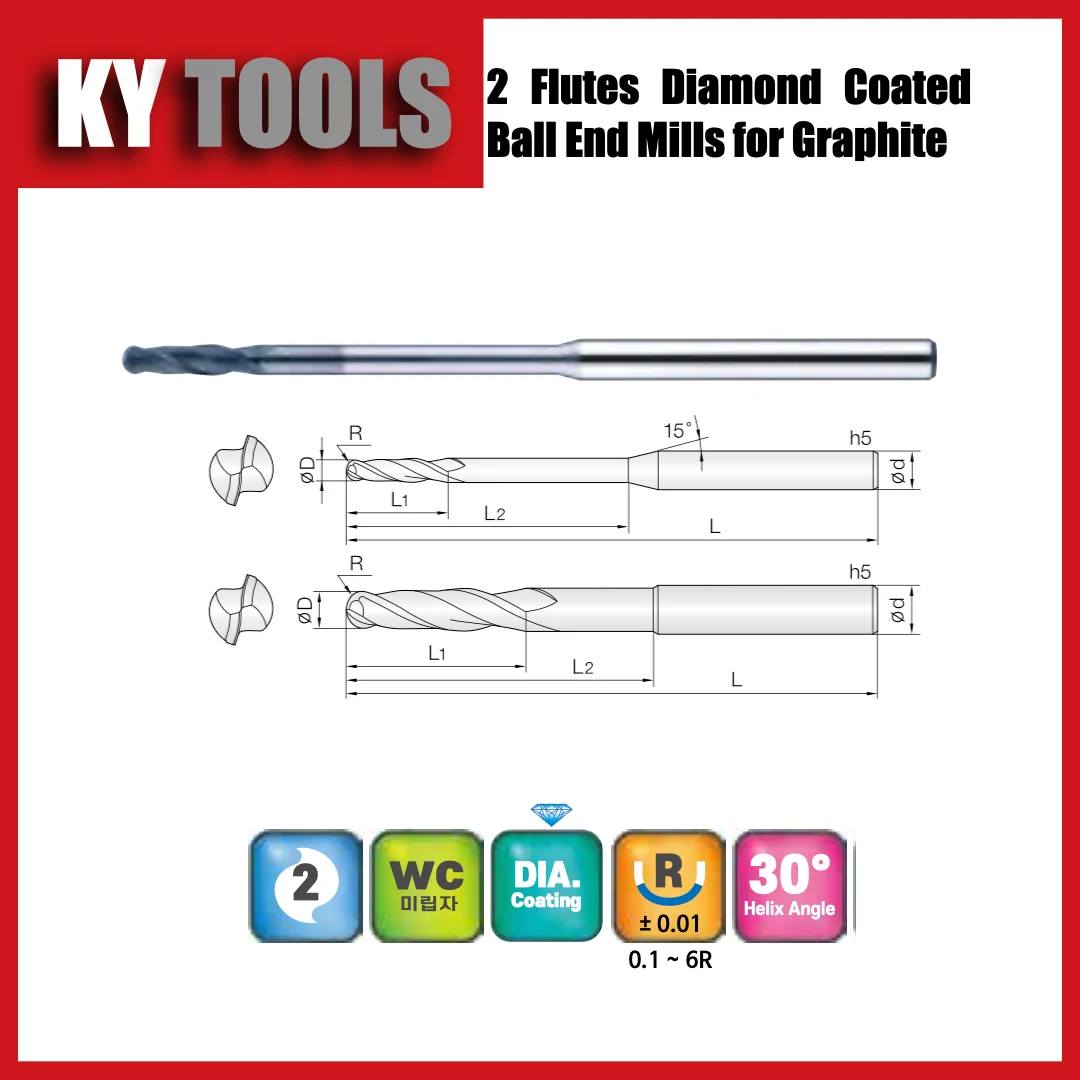
2DBE
2 flutes · Ball nose · Standard reach
Ø0.2–12 mm · 120 sizes
View series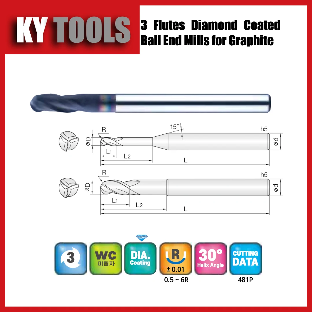
3DBE
3 flutes · Ball nose · Standard reach
Ø1–12 mm · 59 sizes
View series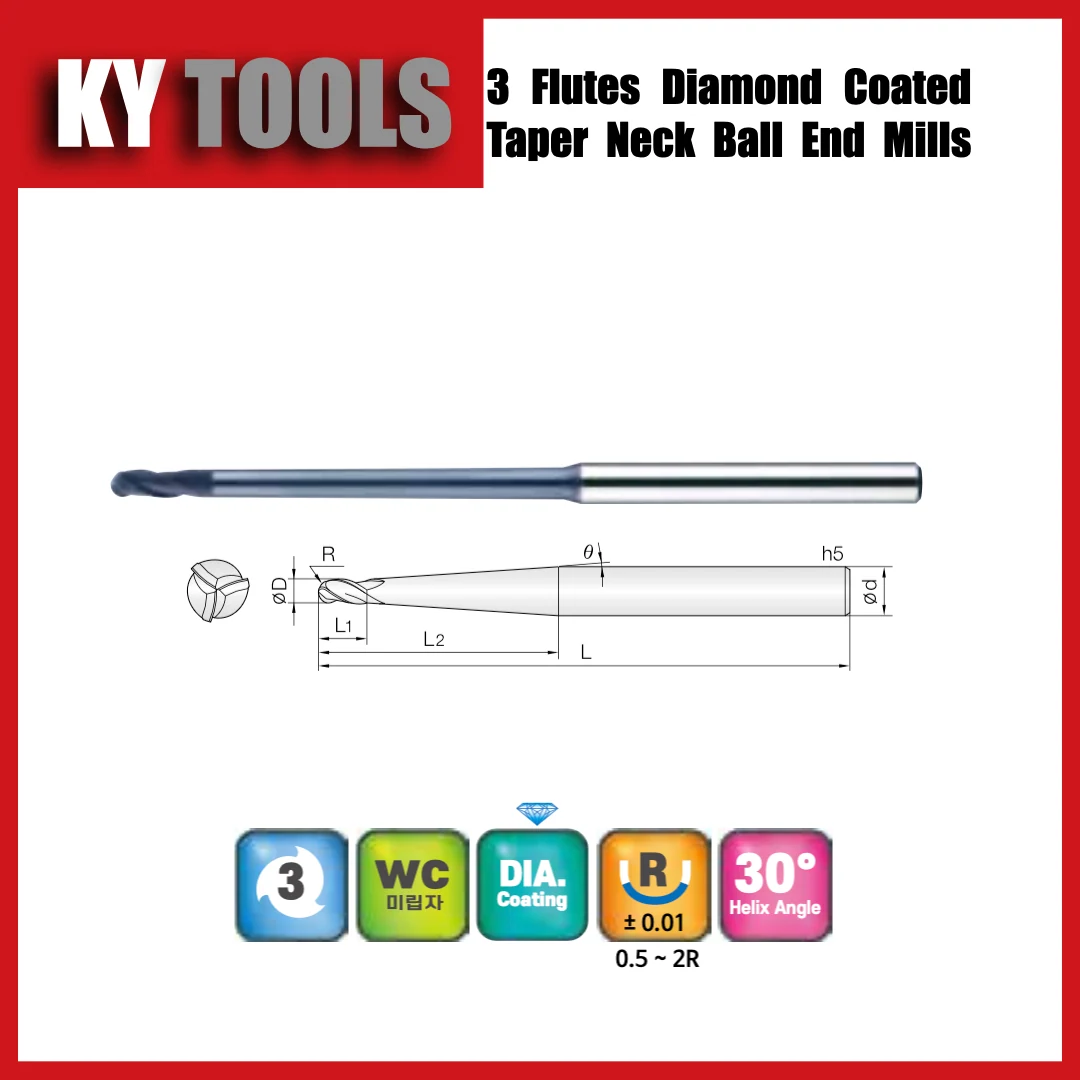
3TBD
3 flutes · Ball nose · Taper neck
Ø1–4 mm · 26 sizes
View series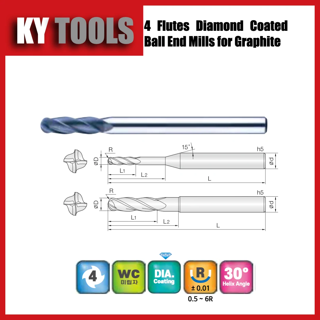
4DBE
4 flutes · Ball nose · Standard reach
Ø1–12 mm · 55 sizes
View series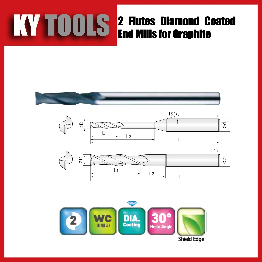
2DEM
2 flutes · Square end · Standard reach
Ø0.2–12 mm · 63 sizes
View series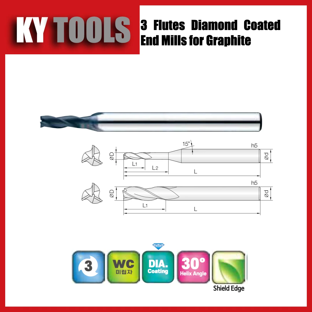
3DEM
3 flutes · Square end · Standard reach
Ø1–12 mm · 32 sizes
View series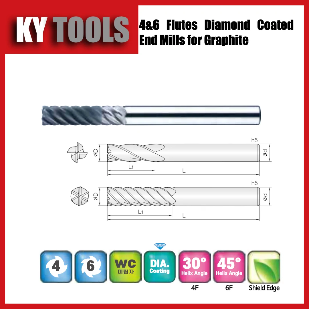
4DEM / 6DEM
4 / 6 flutes · Square end · Standard reach
Ø2–16 mm · 27 sizes
View series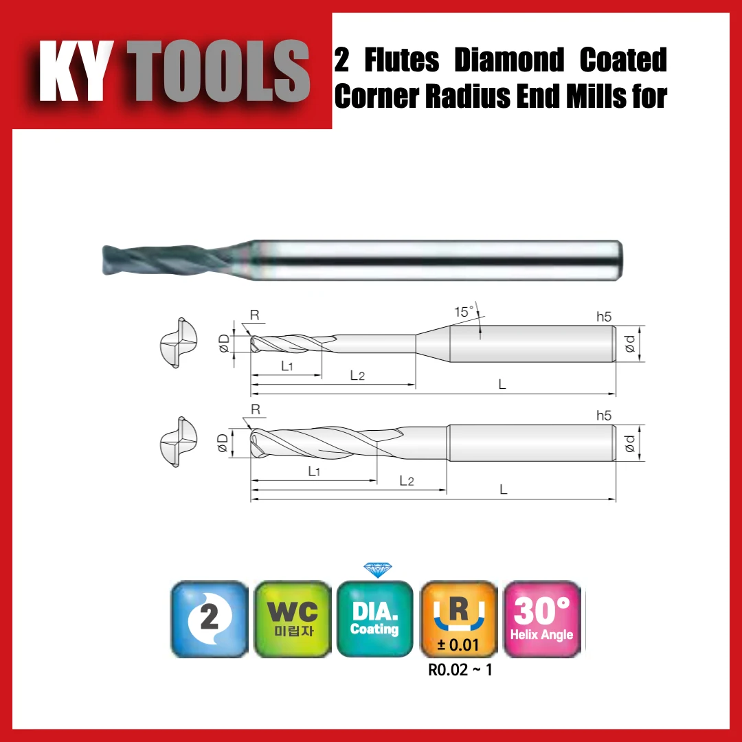
2DCR
2 flutes · Corner radius · Standard reach
Ø0.2–6 mm · 164 sizes
View series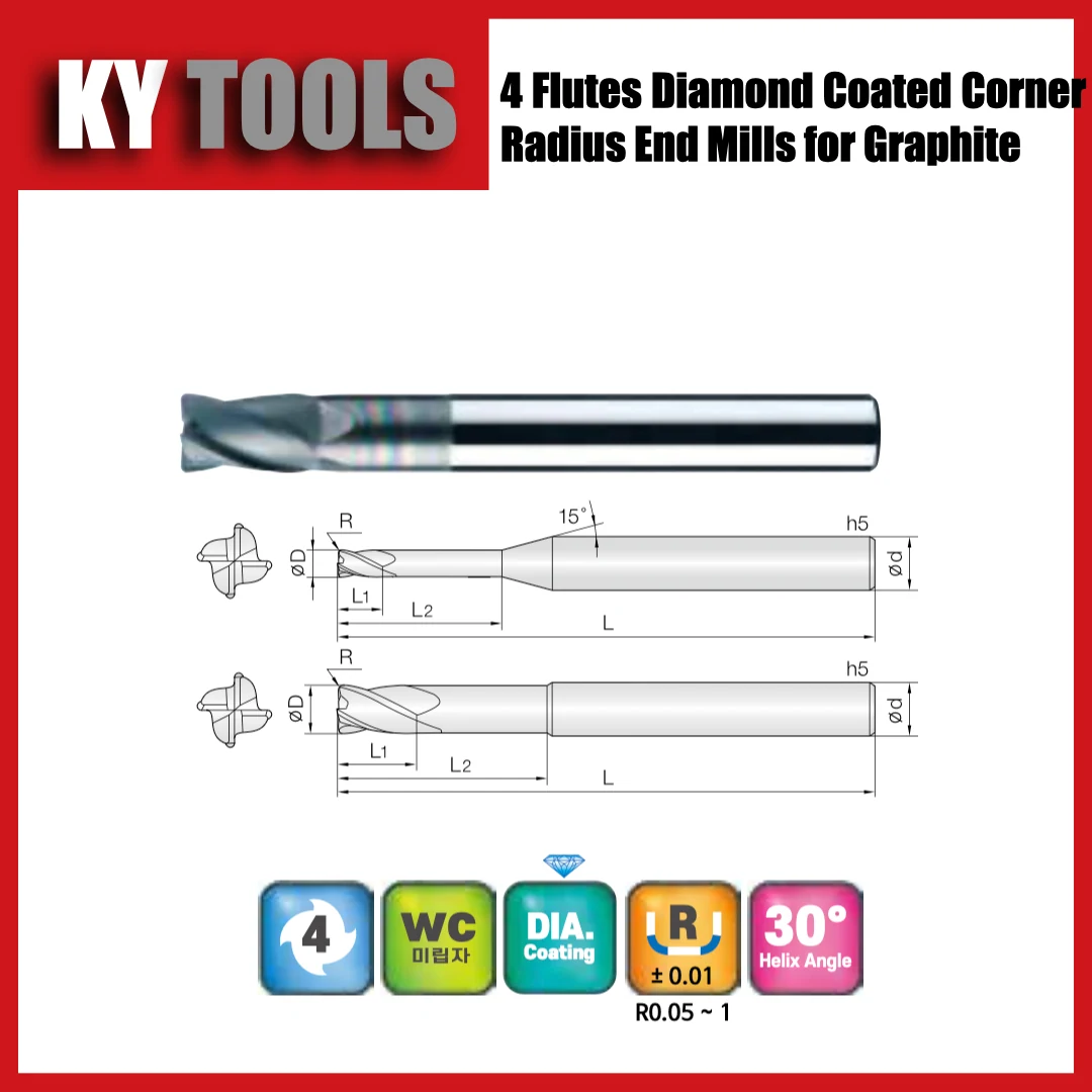
4DCR
4 flutes · Corner radius · Standard reach
Ø2–12 mm · 83 sizes
View seriesDiamond-coated carbide, uncoated carbide or PCD?
CVD diamond is a crystalline diamond coating on a suitable substrate. DLC means diamond-like carbon and is a different coating class; the words “diamond” and “DLC” are not interchangeable purchasing specifications. Ask for the actual coating designation and a graphite application recommendation. PCD is another diamond cutting-tool construction, not a synonym for a coated carbide end mill.
| Tool option | When to evaluate it | What must be verified |
|---|---|---|
| Uncoated carbide | Short trials or low-volume work with modest accuracy demands | Wear and accepted-part cost before assuming the lower price is economical |
| CVD diamond-coated carbide | Repeated electrode milling and abrasive graphite applications | Coating adhesion, finished edge geometry and dimensions after coating |
| PCD tooling | A repeat operation supported by an available PCD geometry | Feature access, edge design, tool price and reconditioning options |
| DLC or a general-purpose metal-cutting coating | Only with application evidence for the proposed tool | Do not substitute a coating name for a graphite trial |
Two tools with the same nominal diameter and coating label can behave differently. Compare the complete tool: substrate, coating, edge preparation, geometry and dimensional control. MOLDINO's D-EPDB/D-EPDR technical announcement describes both a diamond coating and a dedicated carbide substrate intended to improve adhesion. That supports evaluating the system, rather than treating a coating name as a performance guarantee; it does not establish the performance of another supplier's cutter.
For micro features, ask whether the diameter and ball-radius tolerances apply to the finished coated tool. Request an inspection report where those dimensions are critical. Do not apply an assumed coating-thickness correction in CAM when the supplier already specifies the coated diameter.
How many flutes should a graphite end mill have?
Flute count should follow engagement, feed capability and clearance. A two-flute tool can offer more space between cutting edges; higher-flute designs provide more tooth engagements per revolution. Neither observation makes one flute count universally better. Full slotting, side milling and shallow finishing are different load cases.
| Candidate | Useful comparison to make | Main constraint |
|---|---|---|
| 2 flutes | Slots, small features and tool designs with generous flute space | Verify feed per tooth and rigidity for the exact diameter |
| 3 flutes | An intermediate option for compatible graphite geometries | Compare clearance and achievable feed against a two-flute trial |
| 4–6 flutes | Stable side milling or finishing supported by the tool's data | Maintain the intended tooth feed without exceeding machine capability |
At a fixed spindle speed and table feed, adding flutes reduces feed per tooth. Do not replace a two-flute cutter with a four-flute cutter and assume the load on each edge is unchanged. Also check the feed your machine actually reaches on short segments and tight curves; programmed feed alone can be misleading.
Separate cutting length, neck length and tool projection
Cutting length is the portion carrying cutting edges. Neck length provides access below the larger shank. Projection is the distance the assembled tool extends from the holder. These dimensions solve different problems and should appear separately on the RFQ drawing.
Choose only the cutting length the operation needs and the shortest projection that clears the part and fixture. A tapered neck may improve the support available behind a small tip, but the wider neck can collide with cavity walls. Check the entire assembly along the approach, corners and retract moves. A catalog's short-reach cutting data should not be transferred unchanged to a longer assembly.
Graphite speeds and feeds: check the numbers before the first cut
Use cutting conditions for the exact series, diameter, reach and operation as the starting reference. Record spindle speed n, tooth feed fz, flute count z, axial depth ap and radial engagement ae together. A feed value without those conditions is incomplete. Slotting data and light side-milling data should not be treated as interchangeable.
The basic checks are n = 1,000 × Vc / (π × D) and Vf = n × z × fz. Here D is diameter in mm, Vc is cutting speed in m/min, n is rpm, fz is mm/tooth and Vf is feed in mm/min. The following values are deliberately hypothetical arithmetic examples, not recommended settings for an unspecified graphite cutter.
| Calculation example | Inputs | Result |
|---|---|---|
| Peripheral cutting speed | D = 6 mm; n = 18,000 rpm | Vc ≈ 339 m/min |
| Programmed feed | n = 18,000; z = 2; fz = 0.02 mm/tooth | Vf = 720 mm/min |
| Same tooth feed at a spindle limit | n = 12,000; z = 2; fz = 0.02 mm/tooth | Vf = 480 mm/min |
If you keep 720 mm/min after reducing that spindle speed to 12,000 rpm, tooth feed increases to 0.03 mm/tooth. Recalculate instead of changing spindle speed alone. Preserving tooth feed preserves only that arithmetic relationship: lower cutting speed, changed engagement or reduced rigidity still require a new process check.
Ball nose: nominal diameter is not always cutting diameter
At the exact center of a rotating ball end mill, local surface speed is zero. In a shallow cut, the engaged portion can be much smaller than the nominal diameter. For an upright ball tool cutting a horizontal plane within the lower hemisphere, effective diameter at the engagement boundary is Deff = 2 × √(ap × (D − ap)). For D = 6 mm and ap = 0.10 mm, Deff is about 1.54 mm; at 18,000 rpm, local speed at that boundary is about 87 m/min, not 339 m/min. This simplified geometry does not describe every contact point on a tilted tool or a curved surface.
Use the contact geometry and the toolmaker's guidance to select the finishing strategy. Do not increase rpm past the cutter, holder or spindle limits to compensate for contact near the tip. NS TOOL's technical data provides the underlying cutting-speed and ball-contact calculations.
Estimate stepover, then verify the actual finish
For an ideal spherical tool passing over a flat surface, geometric cusp height h = R − √(R² − (s/2)²), where R is ball radius and s is stepover. With R = 3 mm and s = 0.20 mm, the theoretical cusp is approximately 0.00167 mm, or 1.67 µm. This is not a prediction of Ra: graphite particle pullout, wear, runout and surface slope can change the measured finish. Use the calculation to compare paths, then inspect a representative surface.
A trial plan that detects wear before the electrode fails
Define acceptance before comparing tools. Choose dimensions on the electrode that matter downstream, specify an edge-break criterion and agree on how surface condition will be measured. A cutter can still remove material after it has become unsuitable for a finishing tolerance.
- Record the graphite grade and batch, tool code, coating, holder, projection and measured runout.
- Keep the workpiece geometry, program, extraction and inspection method consistent between candidates.
- Measure the first accepted electrode, then inspect at planned intervals using the same datums and method.
- Track dimensional drift, edge damage, accepted quantity, cycle time and tool-change time separately.
- Change one process variable at a time and record the result. Set the tool-change point from the acceptance limit rather than waiting for breakage.
Reserve a known-condition tool for critical finishing when roughing wear could consume the tolerance budget. If the existing process already meets acceptance with one tool, compare the extra tool change against the demonstrated benefit before splitting the operation.
Troubleshoot graphite chipping and dimensional drift
| Observed problem | Inspect first | Controlled next step |
|---|---|---|
| Chipping at an exit edge | Unsupported material, exit direction and cutting-edge condition | Revise the exit path or support; compare one change on a test feature |
| Dimensions drift over a batch | Coated tool dimensions, wear, runout and measurement consistency | Inspect the tool and a reference feature before applying offsets |
| One cutting edge wears faster | Holder cleanliness, runout and clamping | Re-seat and measure the assembly before raising feed |
| Deep walls vary or show marks | Projection, neck clearance and changing engagement | Check deflection and collision clearance; reduce unsupported reach where possible |
| Poor surface despite small stepover | Graphite grade, particle pullout, ball contact and worn edges | Check a fresh edge and the contact strategy before adding more passes |
Dust extraction is part of a repeatable graphite process. Follow the graphite supplier's safety information and the machine and extraction manufacturers' requirements for the installed system. Select dry or wet processing as a complete machine/process configuration; do not improvise coolant use or rely on an open air blast as the dust-control plan. Harvey Performance's graphite machining guide discusses dust and machining considerations in more detail.
Compare cost per accepted electrode, not cost per cutter
A useful purchasing metric is total tool-related batch cost divided by accepted electrodes. Include tool purchases, tool-change downtime and attributable scrap or rework. Compare on the same inspection standard; “parts produced” can hide the cost of rejected electrodes.
| Illustrative purchasing comparison | Tool A | Tool B |
|---|---|---|
| Assumed cutter price, USD | 30 | 90 |
| Assumed accepted electrodes per cutter | 10 | 60 |
| Cutter purchase cost per accepted electrode | 3.00 | 1.50 |
These are invented numbers to explain the calculation, not our prices or measured tool-life claims. Before buying the higher-priced tool, confirm accepted quantity in your own trial and include downtime, delivery reliability and any change in cycle time. A low-volume job may reach a different purchasing decision from a repeat electrode program.
Match the drawing to a Solid Carbide Direct series
Our graphite range includes square, ball nose and corner-radius families, with several flute counts and reach options. Use the series pages to compare dimensions and available cutting references. Request confirmation for the exact order code, finished coating specification and application rather than assuming every size uses identical conditions.
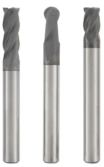
For initial comparisons, 2DEM covers diamond-coated two-flute square tools, 2DBE covers diamond-coated two-flute ball tools, 3TBD offers a diamond-coated taper-neck ball family, and 4DCR covers diamond-coated four-flute corner-radius tools. Availability of a geometry in the catalog is not confirmation that it fits your cavity; verify neck and holder clearance against the drawing.
Questions buyers ask about graphite end mills
Can a regular carbide end mill cut graphite?
It can be evaluated for a short trial, but successful material removal is not proof of economical tool life. Measure wear and accepted-part accuracy before committing a general-purpose cutter to a repeat electrode job.
Is DLC the same as a diamond coating?
No. DLC and crystalline diamond coatings are different material systems. Specify the actual coating and require evidence for the intended graphite application instead of approving a substitution based on the word “diamond.”
Is a ball nose tool best for every graphite electrode?
No. A flat-bottom feature may call for a square end mill, while a ball tool suits curved surfaces. Select the shape from the feature and inspect ball contact and stepover when surface finish matters.
What speed should I use for graphite milling?
Start with the exact toolmaker's conditions for the series, diameter, reach and engagement. Calculate feed per tooth and respect spindle and holder limits. The numerical examples above explain calculations; they are not a universal recipe.
What should be included in a graphite end mill RFQ?
Send the graphite grade, drawing, critical tolerances, tool diameters and radii, cutting and neck lengths, projection, coating requirement, machine rpm limit and operation. Add trial quantity, expected annual volume and delivery location so the quotation can cover both qualification and repeat supply.
Technical references
Diamond coating, dedicated substrate and adhesion.
Cutting speed, feed and ball end mill contact diameter.
Manufacturer guidance on graphite machining and dust considerations.
Distinguishes diamond coatings and diamond tool materials.
Tags